CAD Software for Mechanical Engineering: Programs Compared
CAD software for mechanical engineering compared: FreeCAD, Solid Edge, Creo, NX, CATIA and Tekla classified by use case, modeling and limits.
In this article9
- Is FreeCAD really free?
- Which CAD programs are available?
- Which CAD program is suitable for structural steelwork?
- What does the abbreviation CAD stand for?
- What is the simplest CAD program?
- In which professions is CAD needed?
- Which is the best CAD program for mechanical engineering?
- Frequently asked questions
- Sources
Is FreeCAD really free?
Yes, as far as license costs are concerned. FreeCAD describes itself on its project page as an open-source parametric 3D modeler intended primarily for designing real objects of any size, and advertises with "no licensing fees" as well as "no sign-up, no paywall".[1] According to the project, the program runs under Windows, macOS and Linux and reads and writes many open file formats.[1]
Free of charge in operation, however, does not mean free of cost. For a design department, what also counts are training, internal standards for templates and drawings, data exchange with customers who use other systems, and the question of who helps when a problem arises. A vendor contract with support does not exist with FreeCAD; help comes from documentation and the community. Which free programs exist besides FreeCAD and where their limits lie is a topic of its own; so are the costs per workstation for commercial programs.
Which CAD programs are available?
In mechanical engineering, 3D programs dominate that build parts and assemblies as solid models and derive manufacturing drawings from them. The following overview classifies common systems by what their manufacturers themselves name as their focus. These are manufacturer statements, not independent tests by GoMaschine.
| Program | Vendor | Focus according to manufacturer | Typical use |
|---|---|---|---|
| FreeCAD | Open-source project | [1]Parametric 3D modeler, open source | Getting started, individual parts, smaller assemblies |
| Solid Edge | Siemens | [2]Synchronous technology: direct and parametric modeling combined | Mechanical engineering in mid-sized companies |
| Creo | PTC | [3]Parametric and direct modeling in one CAD environment | Complex parts and assemblies |
| NX | Siemens | [4]Integrated CAD and CAM software from design to manufacturing | Design with connected production planning |
| CATIA | Dassault Systèmes | [5]Portfolio from mechanical design to manufacturing | Large assemblies, surfaces, systems engineering |
| Tekla Structures | Trimble | [6]BIM software, among other things for structural steelwork | Steel and hall construction |
There are other widespread systems besides these, such as SolidWorks from Dassault Systèmes and Inventor from Autodesk. For selection, the list of names matters less than three questions: Which format do your customers require? Should CAM run in the same system? And how large will your assemblies be?
Which CAD program is suitable for structural steelwork?
Structural steelwork calls for programs built to think in profiles, connections and building models, not in individual milled parts. The vendor presents Tekla Structures as BIM software for structural steelwork; drawings are generated directly from the 3D model and updated when the design changes, as a structural steelwork draughtsman describes in a user statement on the vendor's website.[6]
A mechanical engineering CAD package can certainly model a welded machine frame made from profiles. But as soon as halls, platforms or load-bearing structures that must be coordinated with architects and structural engineers come into play, there is a strong case for a BIM-capable structural steelwork system. Which steel suits a machine frame is not a question of software but of material selection; see more in the section on steels.
What does the abbreviation CAD stand for?
CAD stands for Computer-Aided Design. Siemens uses the abbreviation explicitly as "Computer Aided Design" on its NX page and pairs it with CAM for computer-aided manufacturing.[4] In mechanical engineering, CAD today almost always means 3D modeling with derived 2D drawings, bills of materials and assemblies.
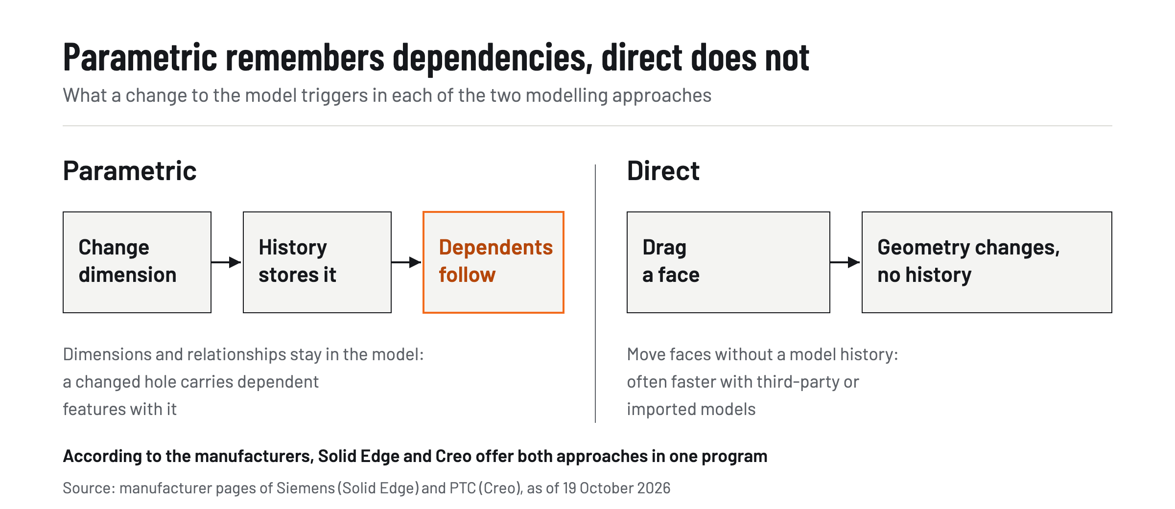
Two terms appear in every comparison. Parametric means: dimensions and relationships remain stored in the model history, so a changed hole pulls the dependent elements along with it. Direct means: you drag and push faces without a history, which is often faster with foreign or imported models.
What is the simplest CAD program?
There is no objectively simplest CAD program; the learning curve depends on what you have used before and what you design. Several vendors advertise ease of use and fast training. These are vendor claims, not an independent finding.
For getting started without license costs, FreeCAD is a good option because you can begin without registration.[1] However, if you later work in a company that uses a commercial system, you will have to learn its operating logic from scratch. It therefore makes sense to practice the program your company or your customers actually use; most commercial vendors offer trial versions for this purpose, Tekla for example 30 days.[6]
In which professions is CAD needed?
CAD is part of everyday work wherever parts, machines or systems are designed and drawn. In mechanical engineering, these are above all:
- Technical product designers and technical system planners who create models and manufacturing drawings
- Designers and engineers in mechanical and plant engineering
- Structural steelwork draughtsmen who plan load-bearing structures and connections with BIM systems
- Production planners and CNC programmers who take CAD data into CAM
Purchasing and maintenance also read CAD data, for example for spare parts or modifications. How design and manufacturing are connected also helps determine which system is worthwhile.
Which is the best CAD program for mechanical engineering?
The best CAD software for mechanical engineering fits your data exchange, your assembly size and your manufacturing. A blanket ranking would be misleading, because the systems have different focuses. These criteria help with the assessment:
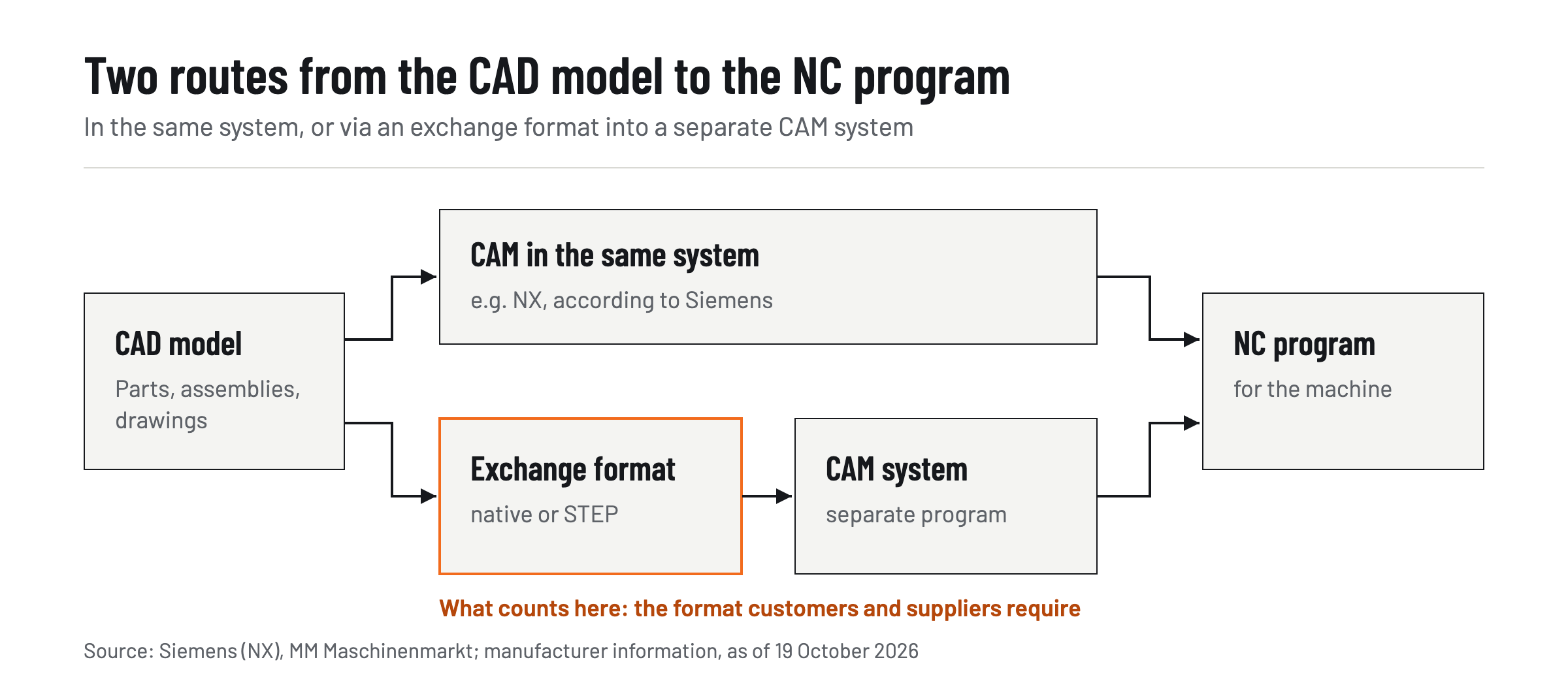
- Data exchange: Which native format and which neutral formats (such as STEP) do your customers and suppliers require? Conversion software can read and write native formats such as CATIA V5, NX and SolidWorks as well as STEP 242, but it does not replace agreeing on the exchange format.[7]
- Modeling: Do you need parametric control, direct editing of imported models, or both, as Solid Edge and Creo reportedly offer?
- CAM and manufacturing: Should NC programming run in the same system, as Siemens describes for NX?
- Assembly size: Large plants with many thousands of parts place different demands on performance and data management than individual parts.
- Operation: Support, training, license model, and the question of who maintains the system in-house.
As a rough guide: FreeCAD for getting started and simple parts, Solid Edge, Creo or NX for end-to-end mechanical engineering design, CATIA rather for very large assemblies and surfaces, Tekla for structural steelwork. Test every claim with your own parts before making a decision. You can find further assessments in the Industry section on GoMaschine.
Frequently asked questions
Is FreeCAD suitable for professional mechanical engineering?
The project describes FreeCAD as suitable for many professional and technical tasks. Whether it fits your operation depends above all on data exchange with customers and on the lack of vendor support.
Does CAD software also run on macOS and Linux?
According to the project, FreeCAD runs under Windows, macOS and Linux. Many commercial mechanical engineering systems are designed for Windows; check the system requirements of the respective vendor.
Do I need a separate program for structural steelwork?
For individual welded frames, mechanical engineering CAD is often sufficient. For halls, platforms and load-bearing structures, BIM systems such as Tekla Structures are designed for the task.
What is the difference between CAD and CAM?
CAD is computer-aided design, CAM is computer-aided manufacturing, for example generating NC programs from the CAD model.
Which CAD software do large mechanical engineering companies use?
This varies from company to company. Commercial 3D systems such as NX, Creo, CATIA, Solid Edge, SolidWorks and Inventor are widespread.